kicad-zcheck: checking the wires a fast signal runs on
Fast signals need wires of the right width for their board. kicad-zcheck checks the wires actually drawn on a KiCad board, and where the return path breaks.
Fast signals, like the ones between FirePod’s processor and its memory, behave best on wires of exactly the right width for the board they run on. Too thin or too wide and some of the signal bounces back.
Those memory wires carry data hundreds of millions of times a second while FirePod works out the beat of whatever’s playing. At that speed, a wire’s width matters as much as its length.
Our board’s design rules asked for the right width, and KiCad, the free circuit design software we use, reported no problems. When we measured what had actually been drawn, most of the memory wires were at the thinnest width the factory can make, and only a quarter of them were close to the target. The fix wasn’t to redraw the board. A board built with thinner layers between the copper makes those thin wires exactly right, and that’s a question for the factory.
kicad-zcheck
kicad-zcheck reads how a KiCad board is built, layer by layer, and checks its fast wires against it.
- Widths per layer: the width each layer needs for the target, on your board or on a different build you’re considering.
- What was really drawn: how much of each signal’s wiring is on target, and which signals are worst.
- Return paths: every signal has a return path through the board’s ground layers. Where a signal changes layer, it shows how far that return has to travel to follow it.
It gives quick estimates for finding problems and comparing options. Your board factory’s own calculation is the final word.
It’s free under the Apache 2.0 license.
Tried on open source boards
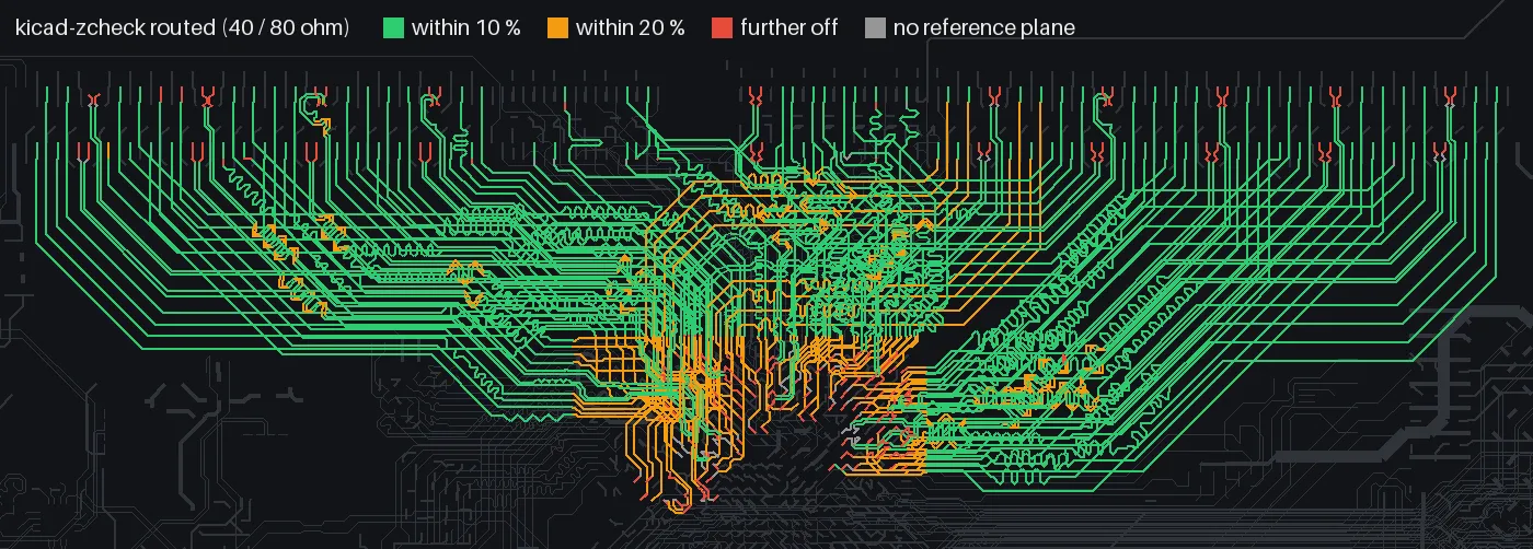
We ran it on two memory boards from Antmicro, a company that publishes its hardware designs. On their 12-layer DDR4 tester, most of the memory wiring on three of the four inner layers is within 10% of a typical target. In the picture, green is within 10% and amber within 20%. The amber patch in the middle is where the wires squeeze out from under the main chip, which is normal.
Checking the numbers
Before release we checked its formulas against published values, exact textbook solutions and a small field simulation of our own. That check found two weak spots in the formulas we’d started with: wires on the outer layers of thin boards read up to a quarter too low, and pairs of wires read up to 31% too high. We switched to more accurate formulas. Single wires on inner layers between two solid copper planes now come within about 3% of the simulation, and pairs within about 8%. An inner layer with a plane on one side only isn’t handled yet: there the numbers read about 17-24% too high, so treat them as an upper limit. Our own board’s result didn’t change: a quarter of its memory wiring was on target before and still is. The full comparison is on GitHub.
More in November
This wraps up the three tools from our circuit board review. Next up are three AI tools, starting on Thursday. Follow along on GitHub, or sign up for updates to hear when FirePod is ready.
More from Firedance
-
kicad-skew: making sure memory signals arrive together
Memory chips need their signals to arrive together, so the wires have to match in length. kicad-skew checks that on a KiCad board with KiCad's own measurements.
-
kicad-fab-tools: circuit board orders, checked
Ordering a circuit board takes a stack of files and careful checking. kicad-fab-tools turns a KiCad design into an order and catches costly mistakes.
-
Music sync and the ECG: measuring a beat
A heart monitor and a music-synced light show solve the same problem: turning a noisy waveform into beats and a rate. Where the two match and where they differ.